JLC PCB's 2020-12-21
So, it took me a while to collect a whole batch of various PCB designs into one order, but they finally arrived today. As I'm still waiting on the LCSC parts, it's time to take some nice pics and write some snippets about what they do.
Tamafoxi
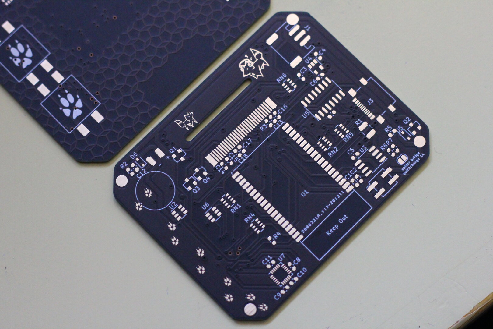
The most important design in this batch, the Tamafoxi, a fully-featured ESP32 handheld game thingie.
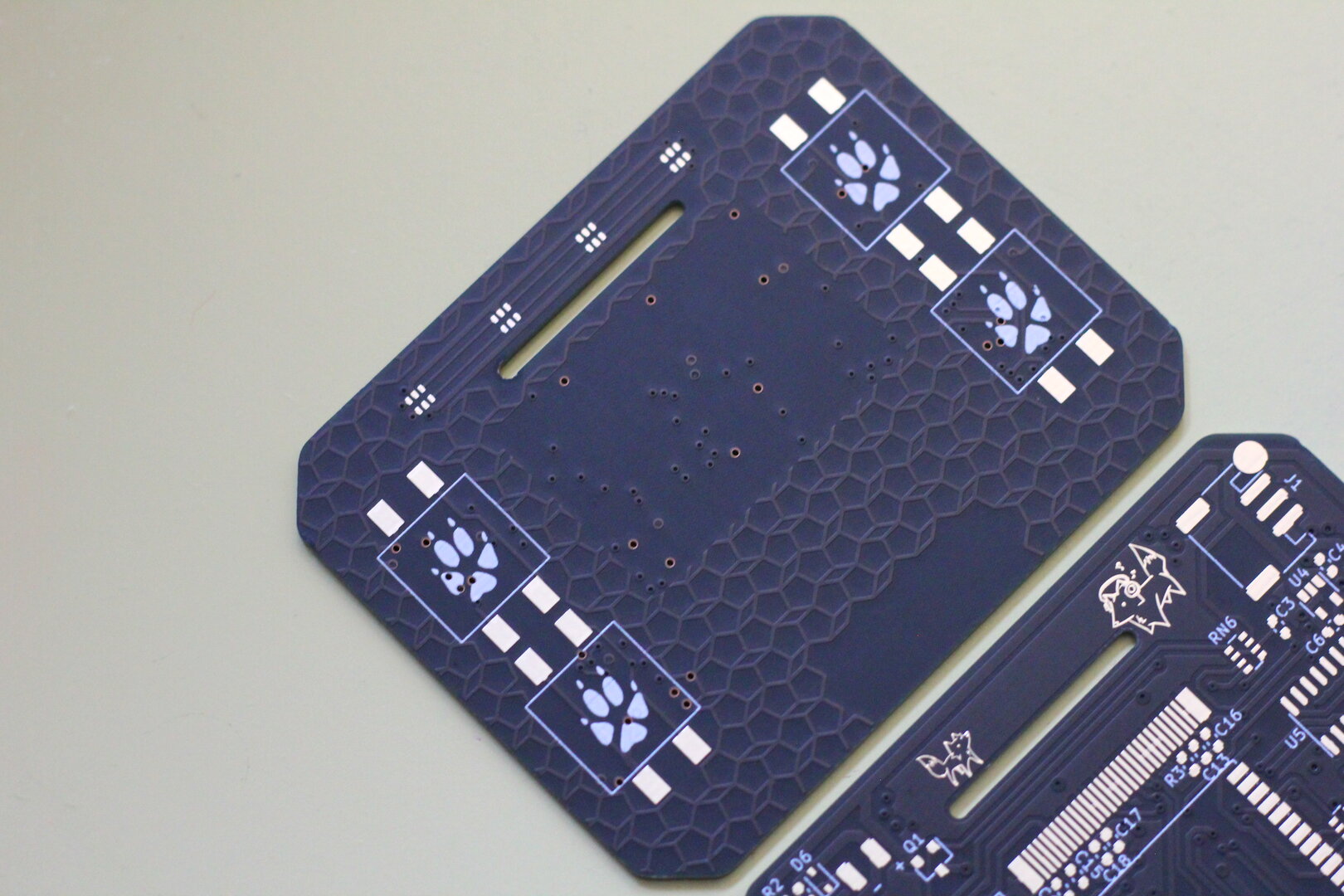
For decoration on the front I experimented with a tiling pentagon design in the copper layer, and routed all the vias and button traces underneath the screen and buttons, so they don't show up on the assembled front.
LiPo V2
My very first PCB design was basically a copy of the TP4056 LiPo charging modules, albeit with a USB Type-C connector instead. The JST footprint for the battery was rotated 180deg but other than that it worked perfectly. Going back to the design though, I really really didn't like how badly readable my schematic was, so I thought it'd be fun to do a redesign.
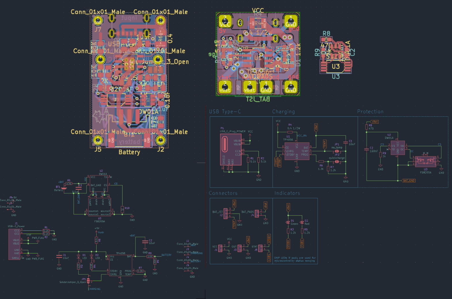
Once my schema was done, the announcement came that JLC would also do SMT assembly on black soldermask (as opposed to just ugly green before), something I've been waiting for ever since they started offering cheap assembly :D
So I designed the PCB in a 20x20 mm square, the minimum for their assembly. Didn't really matter in the end because I ended up panelizing them with 10 modules per board anyways.
Exporting the part placement files from KiCad was a mess, and even then resulted in totally wrong data, but JLC will just correct it for you, and the boards turned out great :)
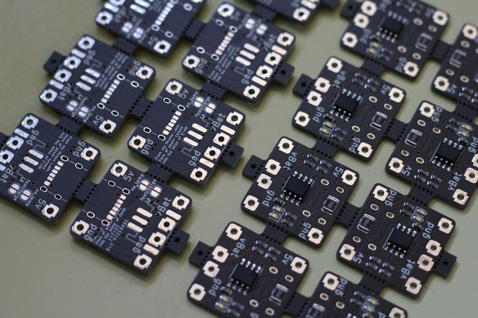
As with all module PCB's it has a vague System Shock Quote, “from my throne room, lines of power careen into the skies of Earth”
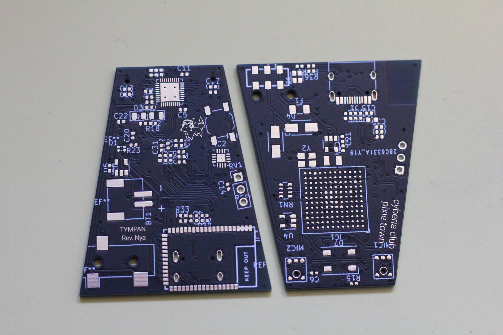
Tympan-Nya
This is a redesign of the Tympan revD, an Open Source/Open Hardware hearing aid development platform, removing the breakout headers, making it USB Type-C and squeezed down to fit in cat ears :3
Designed for a friend but I wanted a batch of them for my eventual PCB showcase wall as well.
MusikFoks
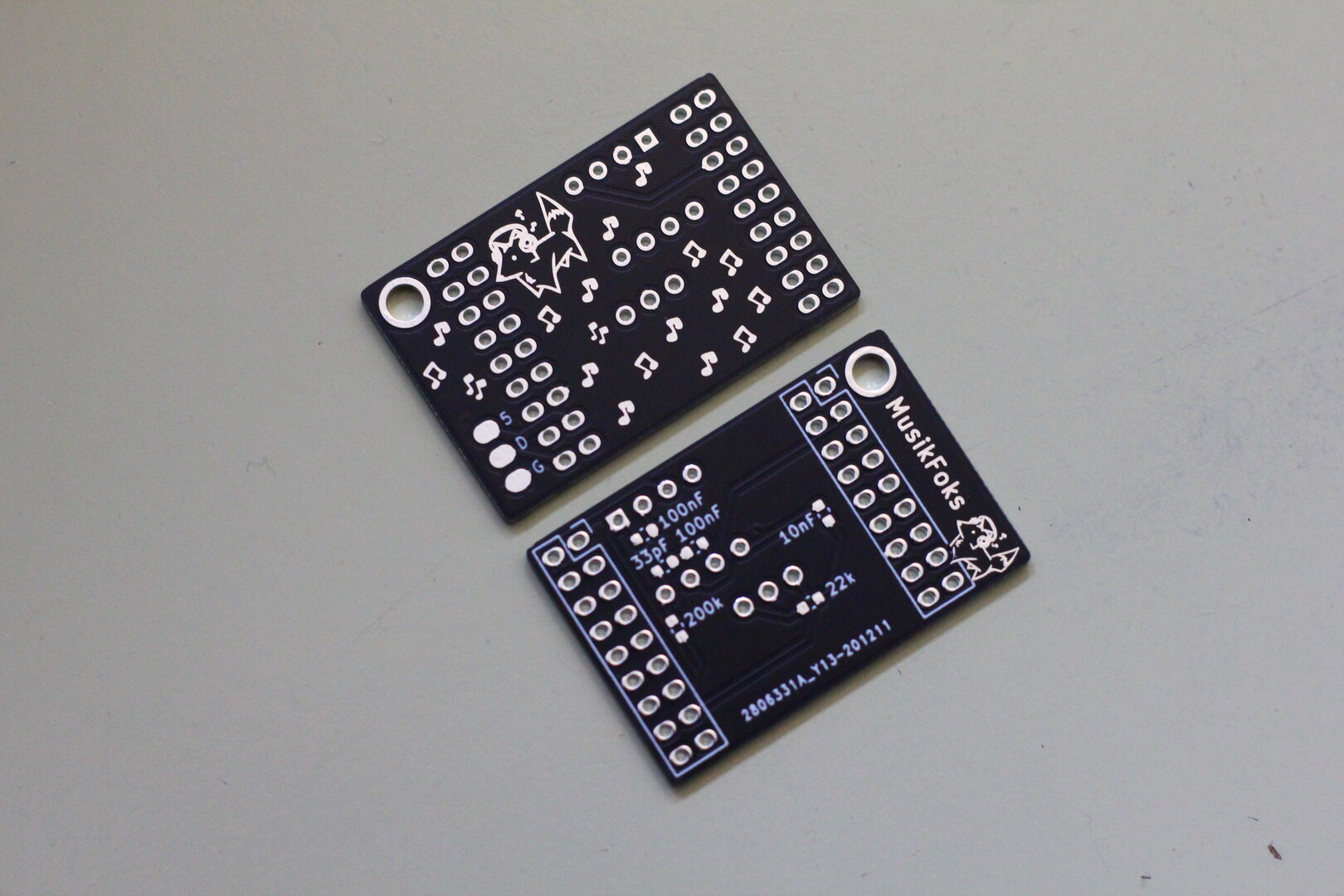
Wanting even nicer LED effects, I thought responding to music would give some nice options. The MSGEQ7 is a nicely contained IC to give a 7 band equalizer output for a microcontroller, although it is kind of annoying to source ($4.95 at SparkFun, or much cheaper AliExpress listings).
This board is designed to fit a standard MAX4466 microphone module, and to piggy-back onto a USBCWrover ESP32 devboard.
USB-C P/D Decoy
My smallest PCB yet, at just 10.5x12 mm. It has a IP2721 chip that speaks on the CC lines to request 20v (as configured by the 100k R1) over USB P/D.
Unfortunately also impossible to source so will have to steal one off an existing AliExpress module... Will be used in a nice silicone cable to power my TS100 soldering iron.
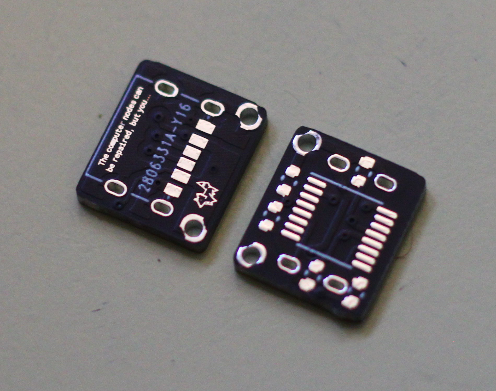
Another vague System Shock Quote, “The computer nodes can be repaired, but you...”